AKZ
Plant Identification System
The AKZ plant identification system is an early predecessor for identifying plants, systems, subsystems, and equipment for plant operators. The use of AKZ is governed by generally established rules. However, AKZ is no longer being further developed or maintained as an identification system. Its application is based on the state of standardization from 1975 and is therefore no longer recommended.
Plant identification based on this system consisted of a 9- to 10-character combination of letters and numbers. Letters were generally used to classify systems and assemblies, while numbers were used for sequential identification.
The AKZ plant identification system distinguishes four hierarchical levels:
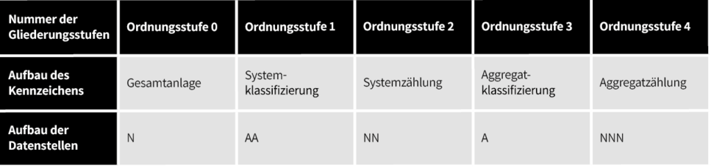
| Hierarchy level number | Level 0 | Level 1 | Level 2 | Level 3 | Level 4 |
| Identifier structure | Overall plant | System classification | System numbering | Equipment classification | Equipment numbering |
|---|---|---|---|---|---|
| Data element structure | N | AA | NN | A | NNN |
Plant identification according to AKZ followed a fixed structure based on hierarchical levels. The level of detail increases from left to right. The structure of the hierarchy levels was alphanumeric. For simplicity, this text uses A to represent letters and N to represent numbers.

Free Quick Check of Your Plant Identification:
With our quick check, you can get an initial assessment in just 5 minutes—free of charge and with no obligation.
AKZ Hierarchy Level 0 – Overall Plant
The first hierarchy level identifies the overall plant and is used for numbering purposes. It consists of a single digit and is used to designate the power plant unit or block.
AKZ Hierarchy Level 1 – Functional Designation
The second of the four hierarchy levels identifies functions, systems, or subsystems of a power plant unit. This hierarchy level consists of two letters. Based on a predefined functional key, systems within power plants were assigned to these letter codes. The first letter from the left denotes the main systems (also referred to as main groups), while subsequent letters are used for further subdivision into subgroups.
The functional key for plant identification according to AKZ is defined, but it is no longer centrally maintained.
Example of the AKZ functional key:
Electrical Engineering Domain
| AKZ | Description |
| A | High-voltage systems for power distribution, grid transformer systems |
| AB | 110 kV 16 2/3 Hz railway power systems |
| AE | 110 kV systems, 50 Hz |
| AH | 50 kV systems |
| AJ | 20/25 kV systems |
| AK | 10 kV systems |
| AP | Generator leads |
| AS | Reactors |
| AT | Unit transformers |
| AU | Coupling transformers |
| AV | Machine transformers |
| B | High-voltage auxiliary power systems and auxiliary transformers |
| BA | HV unit auxiliary power, half-busbar 1 |
| BB | HV unit auxiliary power, half-busbar 2 |
| BC | Medium-voltage main system, start-up system |
| BD | Main distribution boards |
| BE | Main distribution boards |
| BF | Main distribution boards |
| BG | Main distribution boards |
| BH | Unit auxiliary machines and equipment, turbine building |
| BJ | Unit auxiliary main system |
| BK | Unit auxiliary batteries |
Mechanical Engineering Domain
| AKZ | Description |
| P | Fuel handling |
| PA | Coal unloading and storage |
| PB | Coal preparation and conveying |
| PD | Oil unloading and storage |
| PE | Oil conveying and distribution |
| PG | Gas intake |
| PP | Waste unloading and storage |
| PQ | Waste processing |
| PW | Fuel conveying systems |
| PY | Lignite dust conveying |
| Q | Gas turbine systems |
| QA | Turbine and generator casing and rotor |
| QB | Turbine bearings |
| QC | Oil system |
| QD | Combustion chamber |
| QG | Exhaust gas and fresh air supply |
| QJ | Starting device |
| QK | Ignition system |
| QM | Oil firing system |
| QN | Gas firing system |
| QS | Cooling water system |
| QX | Start-up system |
| R | Water/steam circuits |
| RA | Main steam line, HP bypass |
| RB | Hot reheat line, LP bypass |
| RC | Cold reheat line |
| RD | Second reheat |
| RE | Third reheat |
| RF | Extraction for HP feedwater heater |
| RG | Extraction for district heating |
| RH | Extraction for LP feedwater heater |
| RJ | Heat transfer system |
AKZ Hierarchy Level 2 – Functional Numbering
Hierarchy level 2 consisted of two digits. These were referred to as FN numbering and were used for sequential numbering purposes.
AKZ Hierarchy Level 3 – Equipment Classification
The third hierarchy level was used to designate an item of equipment within a subgroup. It consisted of a single letter. Equipment items were classified in power plants according to a predefined equipment key.
Equipment Key – Hierarchy Level 3
| AKZ | Description |
| A | Analytical measurement (chemical analysis, pH value, concentration, etc.) |
| B | Vessels, equipment, heat exchangers |
| C | Control systems |
| D | Working machines, prime movers (pumps, blowers, etc.) |
| E | Electrical measurement (current, voltage, frequency, etc.) |
| F | Flow and quantity measurement |
| G | Weight |
| H | Electrical and signaling devices (horns, rotating beacons, etc.) |
| J | Photoelectric sensors |
| K | Characteristic value calculation, protective devices |
| L | Level measurement |
| M | Special measurements (e.g., moisture, leakage, etc.) |
| N | Room, location, area |
| P | Pressure (including differential pressure and draft) |
| Q | Electrical functional symbols |
| R | Radiation measurement |
| S | Valves, solenoid valves, limit switches, solenoid brakes |
| T | Temperature measurement |
| U | Signal processing from a control module, runtime messages |
| V | Vibration, strain, and length measurement |
| W | Electrical trace heating |
| X | Currently unassigned |
| Y | Speed measurement |
| Z | Piping element |
AKZ Hierarchy Level 4 – Equipment Numbering
Hierarchy level 4 consisted of a total of three digits. These were used to sequentially number the individual types of equipment within a system.
Replacement by the Power Plant Identification System (KKS)
The AKZ plant identification system was replaced by the Kraftwerk-Kennzeichensystem (KKS), as AKZ no longer provided sufficient identification capacity for newer power plants built from 1976 onward.
Existing power plants that still use AKZ-based identification have the option either to fully re-identify their assets using the KKS system or to extend their existing AKZ system by incorporating elements of the KKS power plant identification system.
Replacement by the Power Plant Identification System (KKS)
The AKZ plant identification system was replaced by the Kraftwerk-Kennzeichensystem (KKS), as AKZ no longer provided sufficient identification capacity for newer power plants built from 1976 onward.